


Here are details on one of my latest projects. A Lightning Radar, this was designed by Frank Koofman. After reading his articles on the subject I thought I would give it a try. So far it's taken me a year, and I have only just got it up and running! But it's not finished, The first antenna frame I built is made from wood, and although it will suffice as a test bed, I doubt it will last more than a couple of years, so I have started work on the final one. The design for this comes from a chap called Daniel.... He has just come up with a much better design which is very easy to build. There is a version of the antenna he designed that requires access to a lathe and pipe bending tools, however the new design only requires basic skills, like being able to cut plastic pipe and thread around 400m of cable through the pipes!! so patients is needed. The other big advantage of this antenna design is higher gain and higher Q than both the original designs. One disadvantage is it will be heavy, as there will be around 400m of 1.5mm2 of wire in it... well at least it will not blow away.
So onto my build so far. I started with building the basic antenna. It uses a few bits of wood, some wire, a Christmas tree pot, tool steel, lead and plaster. The antenna should work fine in a loft/attic, however my loft is only just offer a 1m at it's highest, so there is no way the antenna would fit. The only other place for it is on my flat roof. Problem being, I could not screw it down, nor attach it to a soffit. So that is where the Christmas tree pot comes in. Once the antenna was placed in the pot I had to fill it with all the scraps of metal I had. However the antenna still wobbled about. The only solution I could come up with was to fill it with plaster, a hour or so later, one solid antenna :-) I'm not sure how this will fair in the winter, but it will have to do until the next antenna is ready.
The amplifier was brought as a kit from Daniel, I believe he is supplying kits as well as fully built versions.
Here are some pictures of the construction so far, click on the pictures for a larger version...
 |
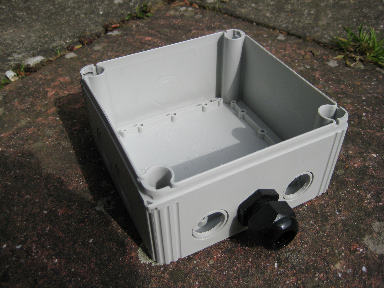
As the amplifier has to live next to the antenna the housing it needs to be weather proof. This is the test housing I chose for the amplifier to live in, and was way too small, as can bee here on the left. Another advantage in building a test version, was to ensure the RJ45 screened cable would work. This was not a good idea, I found major crosstalk issues. So make sure the audio signals are individually screened! and the housing is big enough! |
 |
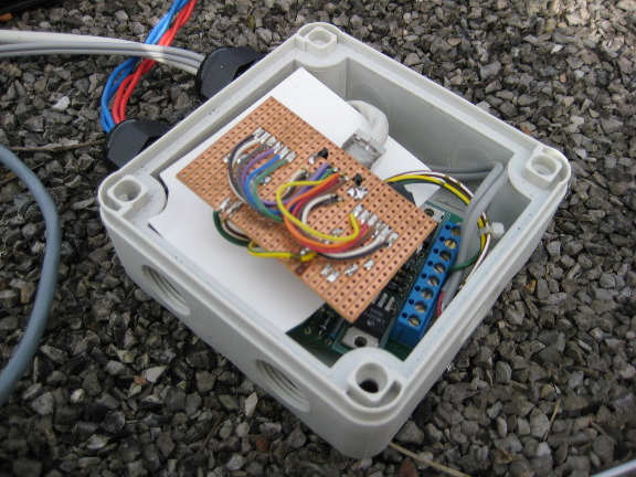
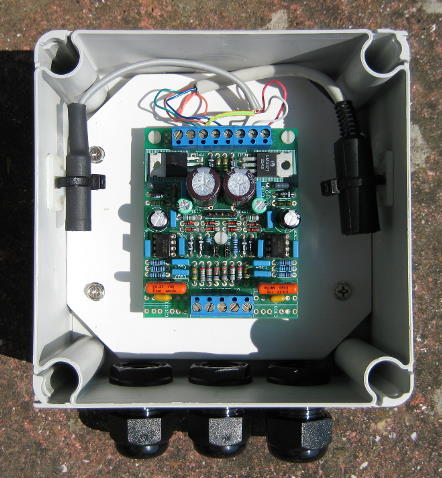
This housing on the other hand leaves loads of space. I have fitted the housing with cable glans, left one for the power connector, centre for the antenna connection and the right one for the power connector, and no crosstalk . I had to use a bigger cable gland for the power connector as this was a mini din, however I still had to remove a small amount inside the cable gland and remove some ridges off the mini din plug, so it would go through the cable gland. |
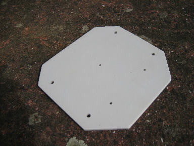 |
As the housing does not have flat bottom inside, I had to make a plate to mount the amplifier on to. This also removes the need for any screws protruding out the bottom of the housing which might affect the weather proofing of the housing. |
 |
Here is the amplifier mounted in the housing complete with it's connectors. I decided to have both the power and the signal wires easily removable. Trying to unscrew them from the top connection block was too much of a pain. However the antenna connection is still a screw connection, due to the signal strength, we need very bit, without losses through connectors. The power is supplied via a 4 pin mini din plug/socket (on the right) and the signal via a 3.5mm stereo jack/plug/socket (on the left). From this picture you can see the larger cable gland for the power connector on the right. |
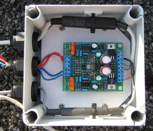 |
Here is the amplifier attached to all its cables! You might notice that the power and audio sockets have moved, It made more sense to have them on these sides once I got it installed. |
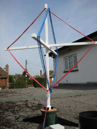 |
My test antenna, in all it's glory, (well, Christmas Tree Pot!) Antenna version 2.0 is on the way.. a much better design.. information to follow.... |
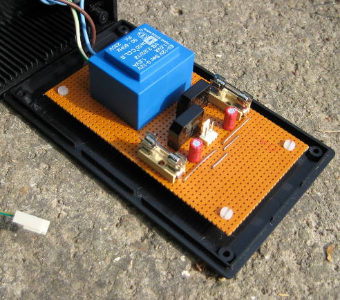 |
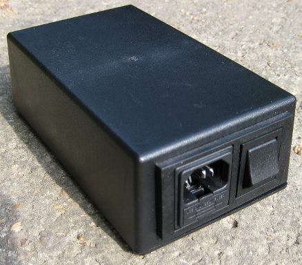
The PSU for the amplifier is housed in a separate case indoors, away for the nasty weather and where the magnetic influence it has, as far away as possible from the amplifier. I have fitted it with two fuses, one for the positive supply and one for the negative supply, just in-case someone cuts the cable going up to the amplifier. I used simple Cat5e stranded cable for the low voltage supply. I tried to get 3 core low voltage/low current cable, to no avail, only chunky mains cable. The Cat5e is plentiful and cheap. |
|
|
A back view of the Amplifier PSU, again as the low voltage, so is the mains fused. |